304 Stainless Steel Machining Guide: Tooling, Parameters and Process Control
Type 304 is often described as a general-purpose stainless steel, but that description can mislead on the shop floor. The alloy is not exceptionally hard when annealed. Its difficulty comes from high ductility, rapid work hardening and relatively low thermal conductivity. An edge that rubs instead of shearing can create a hardened skin and then encounter that harder surface on the next revolution.
Successful 304 stainless machining therefore depends less on chasing a single “correct” speed and more on controlling the whole cutting system: material condition, machine rigidity, tool geometry, chip thickness, coolant delivery and tool-change discipline. The same nominal grade may behave differently as hot-rolled plate, annealed bar, cold-drawn bar or thin tubing. Parameters that work on a rigid turning center may fail on a light machine or on a slender part with excessive tool overhang.
This guide connects those variables to turning, milling, drilling, tapping, design and inspection. Its parameter windows are starting points—not universal guarantees—and must be validated against the toolmaker’s data and the actual production setup.
304 Stainless Steel Machinability and Why the Material Behaves Differently
The central challenge in 304 stainless machining is not simply bulk hardness. Annealed 304 is typically supplied at a hardness that ordinary carbide tools can cut, yet the material deforms strongly in front of the edge. If the edge is dull, the chip is too thin or the programmed path allows dwell, that deformation occurs without efficient chip separation. The newly generated surface becomes harder than the material below it.
In 304 stainless machining, 304 stainless steel machinability is dynamic. The tool may be cutting a locally hardened layer created by the previous pass rather than material in its original condition. A finishing allowance that is too small can be worse than a slightly larger, stable cut because the edge remains inside that affected skin.
Thermal behavior makes the situation more demanding. In carbon steel, a greater share of heat can leave through the workpiece and chip. Austenitic stainless steel conducts heat less effectively, so more heat remains near the cutting edge. Heat promotes adhesion between the work material and tool, softens some tool coatings, changes the effective edge geometry and accelerates notch wear at the depth-of-cut line.
High ductility also produces continuous chips that can block coolant, scratch a finished diameter or disturb a small part in weak workholding. Chip control is therefore a quality issue, not merely housekeeping.
Material characteristic
What happens at the cutting zone
Likely production consequence
Rapid strain hardening
Rubbing creates a harder surface ahead of the next cut
Rising forces, flank wear and sudden edge failure
Low thermal conductivity
Heat remains concentrated near the cutting edge
Adhesion, crater wear and thermal dimensional drift
High ductility
Chips resist breaking and may form a bird’s nest
Surface damage, interrupted coolant and unsafe handling
High thermal expansion
The part grows while warm and contracts after inspection
Bore, length and thin-wall dimensions move after cooling
Tough austenitic structure
Burrs bend instead of separating cleanly
Extra deburring and risk to edge dimensions
These relationships explain why 304 stainless steel machining properties cannot be reduced to one machinability percentage. A stable process needs a sharp edge, enough chip thickness to shear below the affected layer, a rigid load path and a reliable way to remove heat and chips.
303 vs 304 Stainless Steel Machinability and When 304 Is the Better Choice
Material selection for 304 stainless machining should begin with service conditions and downstream manufacturing—not cutting convenience alone. Sulfur-bearing 303 usually produces shorter chips and higher repetition-turning productivity. Standard 304 is less cooperative but offers a better balance of corrosion resistance, weldability and forming performance. The correct grade is the compromise that protects the finished product.
Grade
Relative machining behavior
Important strength
Important limitation
Typical selection logic
303
Shorter chips and lower cutting forces
Efficient high-volume turning
Reduced weldability and lower resistance in some corrosive conditions
Small fittings, shafts and fasteners where machining rate dominates
304
Stringier chips and faster work hardening
General corrosion resistance, fabrication and availability
More demanding tool and heat control
General industrial, consumer, equipment and welded components
Welded assemblies where sensitization risk matters
316/316L
Often equal or more demanding to machine
Better chloride and chemical resistance
Higher material and machining cost
Chemical, marine-adjacent and chloride-exposed applications
The distinction in 303 vs 304 stainless steel machinability is especially important for buyers converting a prototype into volume production. Replacing 304 with 303 may reduce cycle time, but it is not a neutral manufacturing substitution. If the part is welded, exposed to aggressive cleaning chemicals or expected to maintain appearance outdoors, the sulfur modification deserves a service review before approval.
Likewise, 304 vs 316 stainless steel machining should not be decided by assuming that 316 is simply a premium version of 304. Molybdenum improves resistance to localized corrosion in chloride-bearing conditions, but it does not solve machining problems. If the environment does not require that resistance, 304 can provide a more economical combination of material price, availability and processing effort.
Starting stock also matters. Cold-drawn bar offers size consistency but may carry residual stress and a hardened surface; annealed bar may cut more consistently but require more first-pass stock removal. Certification confirms chemistry and mechanical requirements, not identical chip behavior between heats. Recurring jobs should record heat number, tool life and chip form.
Where weight, thermal conductivity and machining rate matter more than stainless corrosion behavior, the decision may move beyond the stainless family. Our aluminum versus stainless steel comparison explains that broader material trade-off.
How to Machine 304 Stainless Steel Without Creating a Work-Hardened Layer
The governing rule in 304 stainless machining—and the practical answer to how to machine 304 stainless steel—is to maintain a true cutting action from entry to exit. Machine rigidity cannot compensate for excessive tool overhang, a sharp insert cannot survive repeated chip recutting, and high-pressure coolant cannot correct a programmed pause at the bottom of a hole.
Cutting-Edge Geometry, Rigidity and Tool Engagement
Use a sharp, positive geometry suitable for austenitic stainless steel. Positive rake reduces cutting force and heat generation, while a prepared edge must still be strong enough for the interrupted or continuous load. The best tooling for machining 304 stainless steel is therefore operation-specific: a stable external turning cut can carry a stronger edge preparation than a thin-wall finishing pass or a small-diameter drill.
Minimize tool and workpiece overhang and check runout at the cutting edge. On a small end mill, slight runout can make one flute carry most of the load while others rub. In turning, unsupported bar and weak clamping create the same cut-rub cycle through vibration.
Entry strategy matters. In milling, arc into the cut when geometry permits and avoid stopping on an engaged edge. A climb-milling path with controlled radial engagement can maintain a more consistent load than repeatedly plunging into full-width slots. In turning, program deceleration so the insert does not dwell against the shoulder. When restarting after an interruption, do not feed the tool gently across a glazed surface; confirm that the edge is intact and re-establish a real cut below it.
Coolant Delivery, Chip Evacuation and Tool-Wear Signals
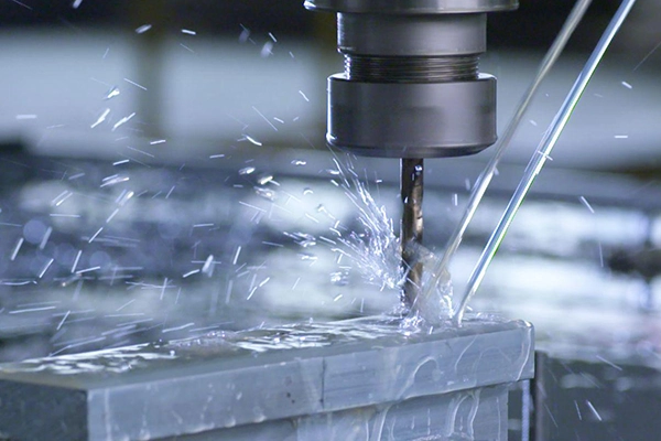
Coolant must reach the cutting zone, not merely wet the enclosure. A long chip can block a poorly aimed nozzle when cooling is needed most. Through-tool delivery supports drilling and milling by removing heat and chips; on a lathe, a focused stream beneath the chip helps lift it away from the edge.
To understand how to prevent work hardening in 304 stainless steel, monitor the process before the part fails. A bright glazed surface, increasing spindle load, rapid flank wear or a growing burr can indicate that the edge is no longer shearing effectively. Blue chips alone are not proof of failure—chips are intended to carry heat away—but blue workpiece surfaces, uncontrolled built-up edge or sudden size drift require investigation.
Tool-life limits in 304 stainless machining should follow dimensional trend and wear condition, not breakage. A worn tool may still pass a roughness check while pushing material and enlarging burrs. For production CNC machining 304 stainless steel, planned replacement usually costs less than sorting an unstable batch.
304 Stainless Steel Machining Speeds and Feeds by Operation
No chart can provide final 304 stainless steel machining speeds and feeds for every machine. In 304 stainless machining, speed depends on tool substrate and coating, feed depends on geometry and engagement, and depth determines whether the edge reaches beneath the hardened layer. The following metric values are conservative starting windows for stable CNC equipment with sharp tools and effective coolant. Toolmaker recommendations take priority.
304 Stainless Steel Turning and Milling Parameters
Operation
Tool and engagement assumption
Cutting speed, Vc
Feed
Starting depth or engagement
Rough turning
Coated carbide, continuous cut
90–150 m/min
0.15–0.35 mm/rev
1.5–4.0 mm radial DOC
Finish turning
Sharp coated or polished carbide
110–180 m/min
0.05–0.15 mm/rev
0.3–1.0 mm radial DOC
General end milling
Coated carbide, rigid setup
70–140 m/min
0.04–0.12 mm/tooth
10–35% diameter radial engagement
Full-slot milling
Coated carbide with strong evacuation
50–100 m/min
0.03–0.08 mm/tooth
Reduce axial depth and validate chip removal
Finish side milling
Sharp carbide, low runout
90–160 m/min
0.03–0.08 mm/tooth
Light radial engagement with meaningful chip thickness
Adjust these 304 stainless steel turning parameters from evidence. Poor chip breaking may respond better to feed or chip-breaker geometry than lower spindle speed. Rapid depth-of-cut notching calls for checks of coolant placement, surface scale and axial insert position. A finishing allowance must remain large enough to cut rather than rub over the hardened surface.
For 304 stainless steel milling parameters, calculate actual chip thickness because low radial engagement can make programmed feed per tooth misleading. Compensation must remain within tool load limits. Full-width slotting needs lower starting speed, strong chip clearance and often a different flute count from adaptive milling; extra flutes are harmful if reduced space traps stringy chips.
Drilling and Tapping 304 Stainless Steel
In drilling 304 stainless steel, the drill must begin cutting immediately and continue with enough feed to avoid rubbing. Use the shortest practical drill, control runout and ensure both cutting lips share the load. Spotting geometry should match the drill so that the outer corners do not contact first. For deeper holes, through-coolant carbide drills offer a major advantage because they cool the edge and move chips out of the flute.
Drill diameter
Carbide speed starting window
HSS-Co speed starting window
Feed starting window
3–6 mm
40–80 m/min
10–20 m/min
0.05–0.12 mm/rev
6–12 mm
50–90 m/min
12–25 m/min
0.10–0.20 mm/rev
12–20 mm
50–90 m/min
12–25 m/min
0.15–0.30 mm/rev
Pecking is not automatically safer. Too many shallow pecks repeatedly return the drill to the hole bottom, where slow re-entry can rub against a hardened surface. Choose the cycle from hole depth, flute capacity and coolant access; clear the chip without dwelling at full depth.
For tapping 304 stainless steel, control the drilled hole size, alignment and lubricant condition. A hole near the tight end of tolerance raises torque sharply. Spiral-point taps help push chips forward in suitable through holes, while spiral-flute taps lift chips from blind holes. Form taps eliminate cutting chips but increase forming torque and require a different pre-hole diameter; they should only be used when the drawing, material condition and thread requirement permit. Thread milling can be a safer choice for larger or high-value holes because diameter can be adjusted and a broken tool is easier to remove.
These windows are part of a process-development sequence, not a purchasing promise. Our custom CNC machining capabilities cover turning, milling and controlled production validation for stainless components.
Tolerances, Surface Finish and Dimensional Stability in 304 Parts
Precision 304 stainless machining requires control of temperature, clamping force and measurement timing. A bore measured hot may not represent its stabilized size. Long shafts can bow as stress releases, while thin walls spring after jaws open. The solution may be balanced stock removal, cooling time or intermediate inspection—not another slow finish pass.
Part feature
Primary risk
Process control
Verification approach
Thin cylindrical wall
Chuck distortion and springback
Low, repeatable jaw force; staged roughing and finishing
Measure released part at several clock positions
Long slender shaft
Deflection, chatter and taper
Tailstock or steady support; sharp tool; controlled DOC
Check diameter along length and straightness after cooling
Precision bore
Thermal growth and tool wear
Stable boring bar, controlled allowance and coolant
Bore gauge at controlled temperature
Cross hole
Exit burr and local distortion
Supported drilling and planned deburring access
Visual magnification plus functional gauge
Sealing face
Built-up edge and directional tool marks
Dedicated finish edge and uninterrupted final path
Roughness and flatness appropriate to sealing function
Small thread
Tap wear, bell-mouthing and burrs
Controlled pre-hole, alignment and tool-life limit
Functional GO/NO-GO gauging where specified
Surface finish must be linked to function. A low Ra value does not guarantee that a sealing face is free from spiral lead, that a sliding shaft lacks torn material or that a passivated surface is free from embedded carbon-steel contamination. Specify roughness only where it affects sealing, friction, fatigue, appearance or cleaning. Elsewhere, an unnecessarily low value adds finishing passes and increases the chance of rubbing.
Deburring also belongs in the dimensional plan. Removing a cross-hole burr can alter a sharp edge or thread start if access was ignored during design. Edge-break dimensions should be achievable and inspectable. For automotive sensor bodies, valve elements and threaded connectors, repeatability of these small features may be more important than cosmetic polish. Related application examples are available on our automotive CNC machining parts page.
Designing and Costing CNC Machining 304 Stainless Steel Components
The largest saving in 304 stainless machining often comes before programming. A deep pocket can force long-reach tooling and rest machining; a blind thread may require five separate cutting and verification actions. One apparently harmless tolerance can decide whether the part finishes in one setup or needs a controlled inspection operation.
Designers should preserve tool access, allow practical internal radii and separate cosmetic requirements from functional ones. These choices keep 304 stainless machining stable. A corner radius should be larger than the cutter radius when possible so the tool can move through the corner rather than stop at full engagement. Deep bores need space for the boring bar and chip evacuation. Closely intersecting holes should be reviewed for drill wandering, breakthrough burrs and weakened walls.
For machining 304 stainless steel, cost is driven by more than cycle time:
Material form and stock allowance determine how much stainless must be removed.
Setup count controls datum transfer, handling and inspection effort.
Tool access determines overhang, rigidity and achievable feed.
Tight tolerances determine finishing strategy and measurement frequency.
Burr locations determine whether deburring is mechanical, manual or specialized.
Batch size determines whether dedicated soft jaws, fixtures and preset tooling are economical.
Surface treatment and cleanliness requirements affect post-machining handling.
A prototype should identify each feature’s real sensitivity. Another finish pass will not solve a thermally moving bore, and a new insert grade will not clear chips packed in a blind thread. If chip behavior changes by material heat, traceability becomes part of process control.
Production should preserve proven datums, tool approach and inspection logic. Improvements can then target the real constraint: tool changes, air cutting, chip evacuation or predictable tool life. That is more reliable than increasing speed until failure and applying an arbitrary reduction.
Commercial evaluation should distinguish piece price from process risk. A low quote may assume generic tolerances, unplanned manual deburring or excessive tool life. A robust quotation reflects the features that consume capacity without repeating a generic RFQ template for every project.
Troubleshooting 304 Stainless Machining Failures
When 304 stainless machining becomes unstable, changing several parameters at once hides the mechanism. Start with the physical symptom, inspect the edge and chip, and then change one dominant variable. The following table provides a practical diagnostic sequence.
Shop-floor symptom
Most likely mechanism
First checks
Corrective direction
Edge chips suddenly after running normally
Tool entered a hardened layer or suffered chip recutting
Programmed dwell, insert edge, coolant blockage
Replace damaged edge and restore continuous cutting
Correct pre-hole and choose suitable chip direction
Thin wall changes after unclamping
Clamping distortion or residual-stress release
Jaw force, stock condition and operation sequence
Use staged, balanced removal and released-part checks
The most useful production record connects tool life, part size, chip form and material heat. That history reveals whether variation originates in the tool, machine, stock or measurement method. It also prevents a temporary correction from becoming an undocumented permanent setting.
In summary, 304 stainless machining succeeds when the edge continues to cut beneath the affected layer, heat and chips leave the interface, and the process accounts for how the part moves after cutting and unclamping. Sharp tooling alone is not enough, and conservative speed alone is not enough. The machine, toolpath, coolant, material condition and inspection method must operate as one controlled system.
For engineers, the practical goal is not to make 304 behave like free-machining 303. It is to retain the corrosion resistance, fabrication flexibility and availability that justified 304 while building a stable route around its cutting behavior. That approach produces better dimensions, more predictable tool consumption and a defensible production cost—the outcomes that make 304 stainless machining commercially successful.
Ready to start
Your next project?
Contact our technical experts today for a customized solution and a tailored quotation.
Our expert team will contact you within 24 hours
to provide a free technical evaluation and solution design, helping you upgrade your production process.
ADDRESS
NO.22,You Yi Road ,Wulian Community, LongCheng Street ,Long gang District ,Shen Zhen