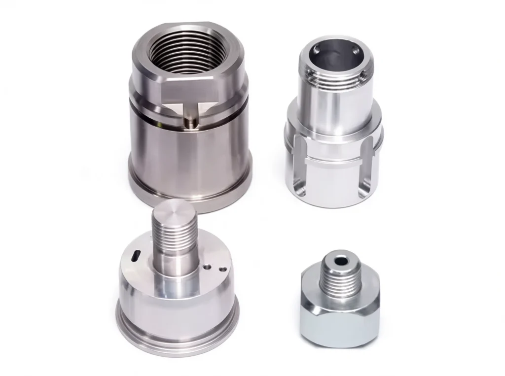
How Swiss CNC Machining Turns Bar Stock into Finished Multi-Feature Parts
A successful Swiss CNC machining cycle begins long before the operator presses Cycle Start. Engineers must translate the drawing into a coordinated sequence involving the bar feeder, sliding headstock, guide bushing, turning tools, live tooling, and sub-spindle. Each decision influences dimensional stability, chip evacuation, cycle time, and inspection results. Unlike a conventional process that moves a tool along unsupported stock, a Swiss-type machine keeps the cutting zone close to the guide bushing while the material moves through it. This guide follows the actual production path—from reviewing functional datums and preparing bar stock to synchronizing machining channels, proving the first article, and controlling process drift during an unattended batch. It is intended for engineers and procurement teams evaluating whether a supplier can convert a complex drawing into a stable, inspectable production process.
Start with the Finished Part Before Building the Swiss CNC Process
Process planning should begin with the finished component, not with a preferred tool list or an existing program. Before selecting operations, the manufacturing engineer must determine which dimensions establish part function, which features must remain related within one setup, and which surfaces can be completed after sub-spindle transfer.
Identify Functional Datums and Critical-to-Quality Features
A drawing review for cnc swiss precision machining should identify:
The primary datum that establishes the rotational axis.
Diameters controlling bearing, seal, or press-fit performance.
Features with runout or concentricity requirements.
Cross-holes whose positions depend on turned diameters.
Threads with functional lead-in or shoulder relationships.
Thin sections that may distort after material removal.
Edges requiring controlled burr direction.
Surfaces that cannot tolerate collet or guide-bushing marks.
Characteristics requiring recorded in-process measurements.
These features become the critical-to-quality, or CTQ, list. The process is then built around protecting those relationships rather than simply minimizing the number of tools.
Divide Features Between the Main Spindle and Sub-Spindle
The engineer must decide where each feature will be produced. Moving an operation to the sub-spindle may make tool access easier, but it also introduces another gripping event and a new source of alignment variation.
Part feature
Recommended station
Process advantage
Primary risk
Front face and pilot diameter
Main spindle
Establishes the initial datum
Incorrect Z reference
Precision outside diameters
Main spindle near guide bushing
High radial support
Tool deflection or taper
Axial bore
Main spindle
Maintains alignment with the turned axis
Chip packing
Cross-hole or external flat
Live-tool station
Eliminates a separate milling setup
Burrs and angular error
Back face and rear chamfer
Sub-spindle
Controls final length after cutoff
Pickoff variation
Rear thread or counterbore
Sub-spindle
Provides direct tool access
Sub-spindle runout
Material choice affects chip formation, thermal growth, surface quality, and tool life. Engineers can review Yueyi’s guide to aluminum materials for CNC machining before finalizing the process plan.
Bar Preparation and Guide-Bushing Setup Decide Whether the Cycle Starts Stable
The CNC program cannot compensate for unsuitable bar stock. Diameter variation, poor straightness, surface damage, or inconsistent material condition can change how the bar passes through the guide bushing. These variations may appear later as taper, chatter, scratches, or periodic dimensional movement.
Check the Material Before It Enters the Bar Feeder
The incoming inspection should verify more than the alloy certificate. A practical bar-stock review includes:
Alloy and temper against the purchase specification.
Actual bar diameter across several positions.
Straightness over the supplied bar length.
Surface scratches, dents, scale, or oxidation.
Lot-to-lot hardness variation.
Compatibility with the selected guide bushing.
Bar feeder capacity and remnant requirements.
Traceability between material records and production batches.
For precision work, the material diameter should also be assessed under realistic shop temperature conditions. A bar that fits correctly during setup can create excessive friction after the machine, coolant, and material reach operating temperature.
Set Guide-Bushing Clearance for Support Without Drag
A guide bushing must support the material close to the cutting point while still allowing smooth axial movement. The correct clearance depends on actual bar diameter, roundness, surface condition, material expansion, and bushing design.
Setup condition
Machine behavior
Likely part result
Corrective direction
Clearance too large
Bar moves radially under cutting load
Chatter, taper, poor runout
Reduce clearance
Clearance too tight
Feed load rises as the bar advances
Scratches, heat, inconsistent length
Increase clearance
Bar is out of round
Drag changes with spindle angle
Periodic size variation
Improve stock quality
Bar is not straight
Load changes during rotation
Vibration and unstable concentricity
Replace or straighten stock
Bushing is contaminated
Movement becomes inconsistent
Surface marks and random size shifts
Clean and inspect the bushing
This setup is one reason a cnc swiss lathe cannot be treated as a conventional turning center with a different tool arrangement. Material support is an active part of the dimensional control system.
Program the Main Spindle, Live Tools, and Sub-Spindle as One Timeline
In a basic turning program, operations often run in a mostly linear order. In Swiss CNC machining, several machine channels may operate at the same time. The program must coordinate spindle speed, C-axis position, tool movement, sub-spindle approach, and bar advancement without creating collisions or unnecessary waiting.
Build the Sequence Around Support and Tool Access
Features requiring the greatest stiffness should normally be machined while the remaining stock still supports the part. Removing a large amount of material too early can leave a flexible section that bends during later drilling, grooving, or cutoff.
A practical sequence often follows these principles:
Establish the front datum.
Machine high-accuracy diameters near the guide bushing.
Complete axial drilling while the section remains stiff.
Produce radial holes, flats, or slots with live tooling.
Finish delicate walls after heavy cutting loads are removed.
Prepare the sub-spindle gripping surface.
Synchronize the spindles and transfer the part.
Cut off the component.
Complete rear features in the sub-spindle.
The exact order changes with geometry. The important point is that swiss cnc programming must reflect part behavior, not merely a convenient list of drawing features.
Synchronize Machine Channels Without Hiding Idle Time
A swiss type cnc lathe may execute main-spindle cutting and sub-spindle backworking concurrently. Synchronization codes prevent channels from entering the same physical area at the wrong time.
Program channel
Typical work
Required synchronization
Collision concern
Main spindle
Turning, drilling, grooving
Waits for live-tool clearance
Tool block versus sub-spindle
Live tooling
Cross-drilling, milling, threading
Waits for C-axis orientation
Tool versus guide bushing
Sub-spindle
Pickoff and backworking
Waits for cutoff completion
Collet versus cutoff tool
Bar feeder
Advances the next section
Waits for part release
Stock versus active tooling
Too many wait codes produce a safe but inefficient cycle. Too few create interference risk. Good programming balances both by mapping which operations can genuinely overlap.
Plan the Pickoff Before Programming the Cutoff
Sub-spindle transfer must be designed as a controlled sequence:
The sub-spindle approaches the prepared gripping diameter.
Main and sub-spindle speeds synchronize.
The sub-spindle collet closes with a defined gripping length.
The cutoff tool separates the component from the bar.
The sub-spindle retracts to a safe work position.
Rear-facing, drilling, threading, or deburring operations begin.
The finished component is released into a catcher or conveyor.
Buyers assessing whether a supplier can manage this complete sequence can review Yueyi’s Swiss CNC machining services and supporting production capabilities.
Follow a Complete Swiss CNC Cycle from Bar Feed to Part Ejection
A process sheet should show more than cutting operations. It should also define how the bar is introduced, how datums are established, when each spindle takes control of the component, and how the finished part exits without damage.
Feed, Clamp, Reference, and Position the Bar
The bar feeder advances material into the working area. The main collet clamps the stock, and the machine establishes the programmed starting position. Depending on the control strategy, the front face may be touched off, faced, or detected through a controlled positioning routine.
The engineer should verify:
Bar-feed length and remnant allowance.
Collet clamping pressure.
Material position relative to the guide bushing.
Tool geometry and wear offsets.
Work coordinate and cutoff position.
Part catcher or ejection readiness.
An error at this stage propagates through the entire component. A small Z-reference mistake may change shoulder locations, thread engagement, overall length, and the sub-spindle gripping position.
Turn, Drill, Mill, and Thread in One Coordinated Cycle
Modern swiss cnc screw machines combine turning and milling functions that previously required several machines. The following map shows how a representative component progresses through the cycle.
Cycle stage
Typical operation
Machine movement
Control variable
Datum preparation
Facing and chamfering
Tool moves toward rotating stock
Initial Z position
Outside profiling
Rough and finish turning
Material moves through guide bushing
Diameter and taper
Axial features
Drilling, reaming, tapping
Axial tool enters the rotating part
Depth and chip evacuation
Radial features
Cross-hole, flat, or slot milling
C-axis indexes while live tool rotates
Angular position
Transfer preparation
Finish pickoff diameter
Main spindle maintains support
Grip length
Part transfer
Synchronization and cutoff
Sub-spindle grips before separation
Spindle phase and location
Backworking
Rear face, thread, or bore
Sub-spindle presents the back end
Overall length and runout
Ejection
Part release and collection
Sub-spindle opens over the catcher
Surface protection
This ability to finish several features in one cycle is central to cnc swiss screw machining. It removes intermediate workholding, but it also makes the original process plan more important because every operation affects the next one.
Complete Backworking Without a Manual Second Setup
Sub-spindle backworking is especially valuable when the rear face controls total length or contains functional threads, bores, or sealing features. The part remains under CNC control rather than being moved to a separate fixture.
Benefits include:
Fewer datum transfers.
Reduced work-in-process inventory.
Lower risk of mixed batches.
Better control of front-to-back feature relationships.
Cutting Parameters Must Follow Tool Engagement and Chip Behavior
Published speeds and feeds are only starting values. Tool overhang, insert geometry, coolant delivery, guide-bushing support, feature depth, and chip exit path all influence the usable parameters on a production machine.
Match Tool Geometry to the Material
Material
Primary machining concern
Tooling direction
Typical failure
Aluminum alloy
Built-up edge and long chips
Sharp positive geometry and polished flutes
Smeared surface
Stainless steel
Work hardening and concentrated heat
Stable feed and heat-resistant tooling
Rapid edge failure
Brass
Edge quality and small-feature control
Sharp tools with controlled cutting pressure
Burrs or overcut
Engineering plastic
Heat and clamping deformation
Sharp edge and limited heat input
Dimensional recovery
When machining aluminum, simply increasing spindle speed does not guarantee a shorter cycle. If chips wrap around the workpiece or tool, the machine may require interruptions, manual cleaning, or frequent insert changes that eliminate the expected productivity gain.
Solve Chip Problems Before Increasing Production Speed
Chip control should be reviewed at every feature where material may become trapped:
Deep axial holes need a reliable evacuation strategy.
Small cross-holes may retain chips inside the bore.
Grooving operations can produce ribbons that wrap around the part.
Cutoff tools need coolant access at the active edge.
Internal threading may require controlled pecking or chip-breaking motion.
Long aluminum chips can enter the guide-bushing or collet area.
A stable cnc screw machining process uses tool geometry, coolant direction, feed strategy, and operation order together. It does not rely on an operator repeatedly opening the machine to remove chips.
Live Tooling Adds Features—and New Timing and Burr Problems
Live tooling allows the machine to produce flats, cross-holes, off-center holes, slots, and milled threads while the part remains in the same cycle. This capability reduces secondary machining, but it introduces C-axis positioning, tool-interference, and cross-feature burr risks.
Separate Axial and Radial Live-Tool Operations
Live-tool orientation
Suitable features
Programming focus
Quality risk
Axial
Off-center holes, front slots, thread milling
Tool length and spindle orientation
Positional error
Radial
Cross-holes, flats, external slots
C-axis angle and radial depth
Burrs at hole intersections
Angular attachment
Inclined holes and special interfaces
Clearance and tool rigidity
Deflection or collision
Tool allocation also affects cycle time. A station may appear convenient in the program but force a longer tool overhang or block access for another operation. On compact swiss turning centers, an interference map should be reviewed before the first program is released.
Control Burrs Where Holes and Slots Intersect
Intersecting features deserve attention during DFM review. A cross-hole entering an internal bore may create a burr in a location that is difficult to inspect or remove manually.
Process options include:
Reversing the order of intersecting-hole operations.
Adding an in-machine chamfering tool.
Applying a controlled back-chamfer.
Adjusting feed as the tool breaks through.
Using a brush or specialized deburring tool.
Defining an acceptable edge condition on the drawing.
“Deburr all edges” is not a complete instruction when the component contains hidden intersections. The supplier and customer should agree on measurable edge requirements.
First-Article Prove-Out Turns a CNC Program into a Production Process
A program may be logically correct and still be unsafe or incapable. First-article prove-out confirms tool positions, channel synchronization, cutting conditions, feature relationships, and inspection methods before automatic production begins.
Prove the Cycle in a Controlled Sequence
A practical prove-out routine includes:
Confirm the tool list, tool orientation, and offset numbers.
Run critical movements at reduced rapid speed.
Check clearance around the guide bushing and sub-spindle.
Verify live-tool rotation and C-axis position.
Test spindle synchronization before cutoff.
Machine one complete component.
Measure all drawing dimensions and geometric requirements.
Review burrs, surface marks, and chip behavior.
Update offsets through an approved method.
Save and identify the accepted program revision.
The first part should not be used only to correct dimensions. It should reveal whether the process can be repeated without abnormal operator intervention.
Convert Measurement Results into Controlled Offset Changes
Inspection result
First item to investigate
Direct offset correction?
All parts show the same diameter error
Tool geometry or wear offset
Usually
Diameter changes periodically
Bar roundness or bushing fit
No
Overall length drifts
Cutoff tool or pickoff position
Only after diagnosis
Runout increases after transfer
Sub-spindle alignment and grip
No
Cross-hole angle is incorrect
C-axis indexing or synchronization
No
Surface roughness deteriorates
Tool edge, chip control, or vibration
Not by size offset
Where components require additional milling, turning, finishing, or inspection operations, Yueyi’s integrated CNC machining capabilities provide a wider manufacturing route beyond the Swiss cycle.
Process Drift Usually Appears Before a Dimension Fails
A capable process is not one that produces a correct first part. It is one that maintains critical dimensions through tool wear, thermal change, material variation, and repeated bar loading.
Read Dimensional Trends as Process Signals
Production symptom
Likely cause
Verification
Corrective action
Diameter slowly increases
Progressive tool wear
Review measurement trend
Controlled compensation or tool change
Size changes during machine warm-up
Thermal growth
Compare cold and stable production
Use a defined warm-up routine
Runout changes suddenly
Collet or bushing contamination
Clean and remeasure
Restore the gripping system
Chatter appears once per revolution
Bent or inconsistent bar stock
Check bar rotation
Replace the affected stock
Back-feature length varies
Sub-spindle pickoff movement
Check grip position
Correct transfer parameters
Burrs increase gradually
Tool edge deterioration
Inspect the cutting edge
Replace tool before failure
Automatic production should use predefined reaction limits. Waiting until a dimension exceeds the drawing tolerance increases sorting, rework, and traceability problems.
Separate Normal Tool Wear from System Instability
Tool wear normally creates a directional trend. Random or periodic variation more often points to bar stock, clamping, temperature, contamination, or synchronization.
This distinction matters because offsetting a random process can make it worse. Before adjusting the machine, the operator should ask:
Is the change gradual or sudden?
Does it affect one feature or several?
Does it repeat at a regular interval?
Did it begin after a new bar or tool?
Is the measurement system stable?
Does the change appear on the main-spindle or sub-spindle side?
Inspection Should Follow the Datums Used Inside the Machine
Inspection planning should be developed with the machining plan. A component can meet individual size limits while still failing because two features are not correctly related to the same functional axis.
Measure Size and Geometric Relationships Separately
The inspection plan may include:
Outside and inside diameters.
Shoulder and overall lengths.
Thread gauges and thread position.
Radial and axial runout.
Concentricity or coaxial relationships.
Cross-hole position.
Surface roughness.
Burr and edge-condition inspection.
Visual checks for guide-bushing or collet marks.
For cnc swiss screw machine parts, front-to-back relationships deserve particular attention because they may cross the main-spindle and sub-spindle portions of the cycle.
Set Inspection Frequency According to Risk
Inspection stage
Typical scope
Purpose
First article
Full drawing and CTQ review
Approve setup and program
After tool change
Features affected by that tool
Confirm new offset
In-process inspection
Selected CTQs and trend data
Detect drift
Last-piece inspection
Critical dimensions and appearance
Verify end-of-run condition
Final inspection
Drawing, documentation, quantity, packaging
Release shipment
Inspection frequency should consider tool life, tolerance sensitivity, batch size, historical capability, and the consequence of a nonconforming feature.
Medical Components Need Traceability, Not Only Small Dimensions
Medical-device parts often combine narrow diameters, thin walls, small holes, threads, and stringent edge requirements. However, size alone does not make a process suitable for medical supply.
A controlled Swiss CNC machining route should address:
What Buyers Should Confirm Before Releasing a Production Order
A detailed RFQ allows the supplier to assess risk before quoting. Buyers should provide more than a model and annual quantity.
Information to Include in the RFQ Package
Controlled 2D drawing and 3D model.
Material grade, condition, and approved alternatives.
Functional datums and critical dimensions.
Thread specifications and gauge requirements.
Surface roughness and cosmetic requirements.
Edge-break and burr criteria.
Heat treatment, coating, or passivation requirements.
Prototype, batch, and annual quantities.
Inspection report requirements.
Material certification and traceability expectations.
Packaging and cleanliness requirements.
Target delivery schedule.
Evidence to Request from the Supplier
Procurement concern
Useful supplier evidence
Process feasibility
DFM review and proposed operation sequence
Complex-feature capability
Main-spindle, sub-spindle, and live-tool plan
Tolerance stability
First-article results and process data
Batch consistency
Tool-life and inspection strategy
Traceability
Material, program, and inspection records
Cost control
Cycle-time and one-setup manufacturing plan
Delivery reliability
Capacity, bar supply, and production scheduling
A low unit price does not indicate a low total purchasing cost if the process depends on manual rework, repeated sorting, or unstable secondary setups.
Google People Also Ask Questions About Swiss CNC Production
The following questions were verified in Google’s People Also Ask results for the target query. A salary-related question also appeared, but it was excluded because it does not support an industrial engineering or purchasing decision.
What Is Swiss Style Machining?
Swiss-style machining is a CNC turning method in which the bar stock moves through a guide bushing while cutting occurs close to the supported point. This reduces unsupported material length and helps control deflection when machining slender components. Modern equipment can combine turning, drilling, milling, threading, cutoff, and sub-spindle backworking within one automated cycle.
What Are the Key Differences Between CNC and Swiss Machines?
A Swiss machine is also a CNC machine. The more useful comparison is between a Swiss-type CNC lathe and a conventional fixed-headstock CNC lathe.
Comparison
Swiss-type CNC
Conventional CNC lathe
Material movement
Bar moves axially through a guide bushing
Workpiece remains primarily fixed in the spindle
Cutting support
Cutting occurs near the guide bushing
Support depends on chucking and workpiece length
Typical strength
Slender, small-diameter, multi-feature parts
Shorter or larger turned parts
Multi-operation capacity
Often includes live tools and sub-spindle
Depends on machine configuration
Setup sensitivity
Strongly affected by bar and bushing condition
Strongly affected by chucking and workholding
What Is a Swiss CNC Machinist?
A Swiss CNC machinist sets up and controls Swiss-type CNC equipment. The role may include selecting guide bushings and collets, installing tools, setting offsets, proving multi-channel programs, verifying spindle transfer, inspecting first articles, and monitoring production trends. Experienced machinists also distinguish tool wear from problems caused by bar stock, temperature, chip control, or the gripping system.
Turn the Drawing into a Stable, Inspectable Production Cycle
Effective Swiss CNC machining connects drawing interpretation, material preparation, guide-bushing control, multi-channel programming, cutting strategy, sub-spindle transfer, and inspection into one repeatable process. Cycle time matters, but speed should not be gained by accepting poor chip evacuation, hidden burrs, uncontrolled offsets, or excessive operator intervention. Before requesting a quotation, provide the supplier with the drawing, material condition, functional datums, critical tolerances, expected quantities, inspection requirements, and delivery targets. Yueyi Precision can then review feature access, bar-stock requirements, tool allocation, transfer strategy, secondary processing, and quality controls to determine whether the part is suitable for stable Swiss CNC production.
Ready to start
Your next project?
Contact our technical experts today for a customized solution and a tailored quotation.
Our expert team will contact you within 24 hours
to provide a free technical evaluation and solution design, helping you upgrade your production process.
ADDRESS
NO.22,You Yi Road ,Wulian Community, LongCheng Street ,Long gang District ,Shen Zhen