Custom Aluminum Extrusion Design Guide: Engineering Profiles for Stable Tooling, CNC Accuracy and Lower Production Risk
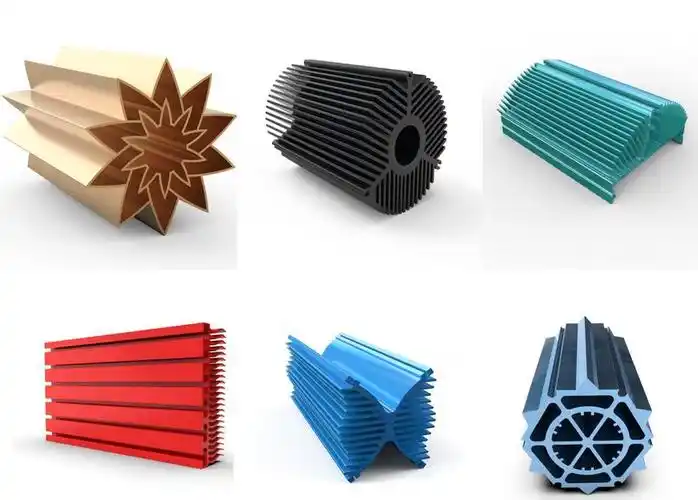
A successful aluminum profile must do more than match a CAD cross-section. It must flow consistently through the die, survive quenching and stretching, provide useful machining datums, accept the specified finish, and assemble without costly sorting or rework. This Custom Aluminum Extrusion Design guide explains how engineers and industrial buyers can convert functional requirements into a production-ready profile. It covers alloy selection, wall balance, radii, solid and hollow geometry, interlocking features, tolerances, CNC allowances, cosmetic surfaces, trial validation, and RFQ preparation. The objective is not to impose a universal dimension rule. Instead, it is to show how geometry, process capability, inspection conditions, order volume, and finished-part requirements interact before tooling is released. Early DFM decisions generally offer more leverage than corrections made after extrusion trials begin.
Start with Functional Requirements Before Drawing the Extrusion Cross-Section
Profile development should begin with function, operating conditions, assembly, and delivery state. Drawing the section first often creates unnecessary ribs, inaccessible cavities, weak tongues, or features that still require machining.
Translate Product Functions into Profile Features
Each geometric feature should have a measurable purpose. That discipline helps remove material that adds tooling difficulty without improving performance and identifies where testing is needed.
Product requirement
Possible profile feature
Validation method
Structural support
Rib, web, or closed section
Load calculation and physical test
Component location
Slot, boss, or reference face
Assembly and dimensional inspection
Heat transfer
Fins and increased surface area
Thermal analysis and temperature test
Cable management
Internal channel
Cable-fit and access review
Fast assembly
Interlocking or snap-fit feature
Insertion and retention testing
Cosmetic enclosure
Controlled visible face
Approved appearance sample
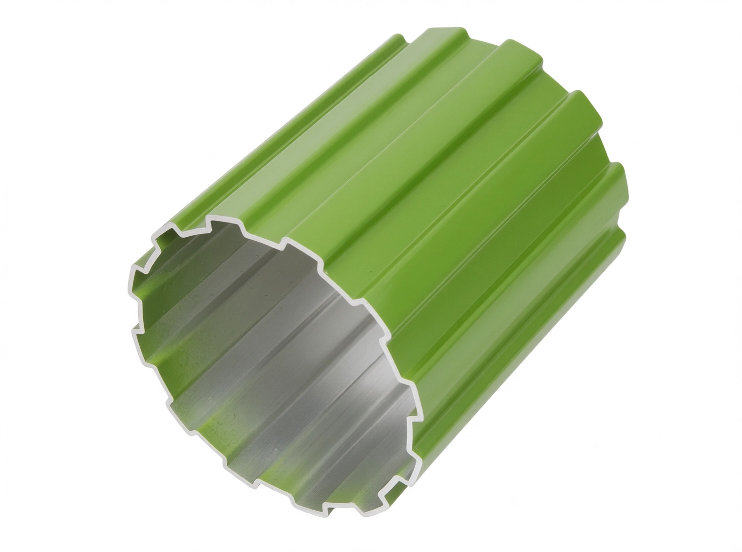
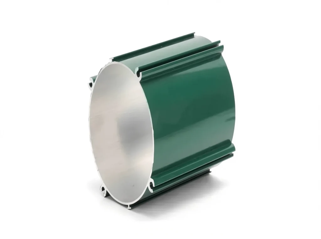
For example, interlocking aluminum extrusions can reduce fasteners, while oval aluminum extrusions may form an enclosure. Both shapes are useful only when their function justifies the die and inspection requirements.
Define Production Volume and the Required Delivery Condition
A supplier cannot optimize custom aluminum extrusion from the cross-section alone. Tooling strategy and unit economics change according to annual demand and how much work remains after extrusion.
Prototype, pilot-run, and annual production quantities
Extrusion supply length and final component length
Required alloy and temper
Cutting, drilling, tapping, milling, and deburring scope
Anodizing, powder coating, painting, or mechanical finishing
Critical dimensions and cosmetic zones
Inspection documents, packaging, and export destination
The buyer should state whether it needs mill-length material, cut blanks, or finished custom extruded aluminum components. This prevents an extrusion-only quotation from being compared with a complete manufacturing quote.
Select Alloy and Temper by Balancing Extrudability, Strength and Finishing
Alloy selection affects metal flow, achievable geometry, press productivity, mechanical performance, machining behavior, corrosion resistance, and surface appearance. Choosing the strongest listed alloy without considering the cross-section can increase tooling corrections or restrict thin and intricate features.
Compare Common 6000-Series Alloys for Industrial Profiles
This comparison is directional, not a substitute for material standards or application testing. Actual properties depend on temper, processing history, and the governing specification.
Design consideration
6063
6061
6005/6005A
Relative extrudability
Generally favorable
More demanding
Between typical 6063 and 6061 behavior
Strength potential
Moderate
Higher
Medium to high
Decorative finish
Often selected for anodized appearance
Must be reviewed against appearance needs
Confirm with supplier and finish standard
Complex thin sections
Often advantageous
Requires closer DFM review
Evaluate by actual geometry
Common decision driver
Appearance and intricate profiles
Structural duty and machining
Structural profile applications
Review aluminum alloy extrusion as a material-and-geometry decision. No alloy can rescue an unsupported tongue or guarantee assembly strength.
Why Temper Must Be Defined with the Alloy
Calling out an alloy without its temper leaves the requirement incomplete. Temper influences strength, stability, forming behavior, and downstream operations.
Strength: Confirm the required condition from an applicable material standard.
Straightening: Consider how quenching and stretching support the selected temper route.
Machining: Plan stock removal and clamping for the delivered material condition.
Finishing: Confirm that heat treatment and surface preparation support the required appearance.
Material certification should identify alloy, temper, standard, and lot. Structural or safety-related drawings should also define the required test evidence.
Balance Wall Thickness to Improve Metal Flow and Dimensional Stability
Balanced walls encourage more uniform metal flow and cooling. This does not mean every wall must have an identical nominal thickness. It means avoiding unnecessary mass concentrations and providing gradual transitions where functional requirements demand different sections.
How Uneven Walls Affect Extrusion Behavior
Thick regions can flow and cool differently from thin regions. The resulting imbalance may appear as section distortion, angular movement, bow, twist, or inconsistent machining stock.
Design condition
Process effect
Possible result
Abrupt thick-to-thin transition
Uneven flow velocity
Section distortion
Heavy local mass
Uneven cooling and contraction
Bow or twist
Long unsupported thin wall
Low stiffness after die exit
Waviness or handling damage
Thin wall beside a heavy boss
Differential movement
Angular or positional variation
Asymmetric material distribution
Unbalanced quenching response
Longitudinal instability
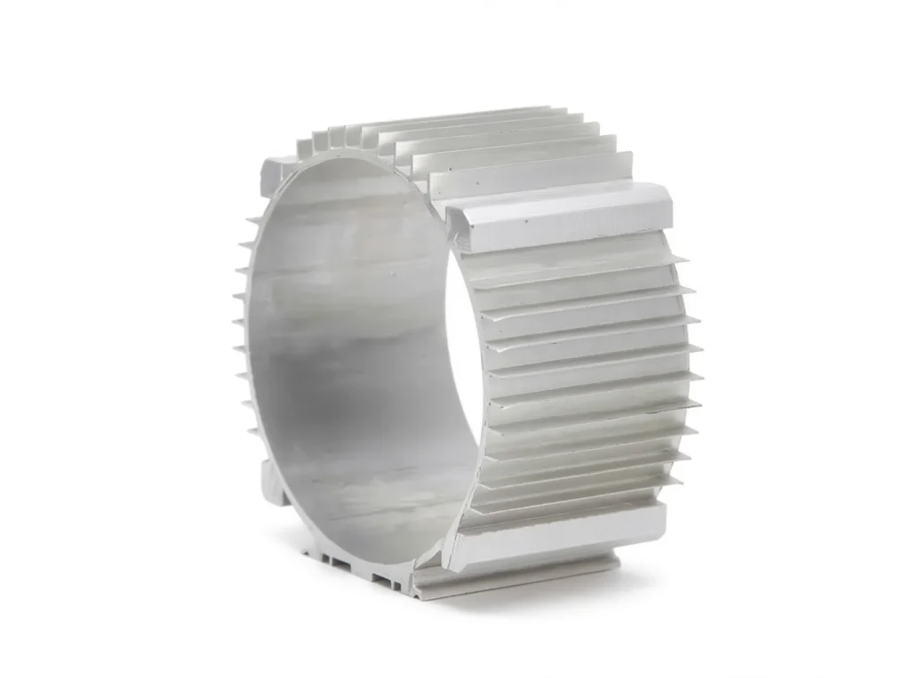
Wide aluminum panel extrusions require particular attention because broad, relatively thin faces can magnify flatness and cosmetic issues. Adding material everywhere is rarely the best solution; it can increase weight while creating new cooling imbalances.
Use Gradual Transitions Instead of Abrupt Mass Changes
During Custom Aluminum Extrusion Design, review the full section rather than optimizing each feature independently.
Blend thick and thin areas through practical transitions.
Remove local mass that has no structural or machining function.
Relate rib thickness to the supporting wall and load path.
Avoid placing a critical flat surface beside a severely unbalanced region.
Add machining stock locally instead of thickening the whole profile.
Ask the extruder to review flow balance before tooling release.
Simulation may support this review, but it is not production approval. Die construction, alloy, quenching, stretching, and press experience remain essential.
Design Radii, Corners and Ribs to Protect the Die and Profile
Sharp internal geometry is difficult for metal flow and can create stress concentrations or fragile tooling features. Appropriate radii improve filling, strengthen feature transitions, and simplify die manufacture while still preserving functional edges where they are genuinely required.
Where Internal and External Radii Add Manufacturing Value
Feature location
Engineering value of a radius
Internal corner
Supports filling and reduces local stress concentration
Rib root
Creates a stronger transition into the parent wall
Slot base
Reduces stress at the die-tongue root
External handling edge
Improves safety and reduces damage sensitivity
Machined transition
Provides cutter access or a controlled edge condition
Agree radius values with the supplier because feasible geometry depends on scale, alloy, tooling, feature depth, and appearance. A copied universal minimum may be inappropriate.
Use Ribs for Real Load Paths, Not Visual Complexity
Ribs can improve stiffness efficiently, but poorly positioned ribs can unbalance the section or create narrow regions that are difficult to fill and inspect.
Recommended practice
Practice to avoid
Place ribs along a verified load path
Add ribs without a functional reason
Use a manufacturable root radius
Specify a sharp rib-to-wall junction
Review cooling balance across the section
Concentrate ribs and mass on one side
Leave room for gauges and cutting tools
Create inaccessible narrow channels
Validate stiffness at system level
Assume more aluminum always means better performance
This discipline is especially useful for custom aluminum extrusion profiles that integrate mounting, guidance, and enclosure functions in one continuous cross-section.
Choose Solid, Hollow or Semi-Hollow Geometry with Tooling Risk in Mind
The same product function may be achieved through solid, hollow, or semi-hollow geometry, but each category changes die construction, metal flow, correction strategy, and cost. Classification should therefore be resolved with the tooling supplier rather than inferred only from the visible opening.
Compare the Three Main Profile Categories
Profile category
Typical tooling approach
Main advantage
Primary design risk
Solid
Solid die
Relatively direct tooling structure
Asymmetric sections can still distort
Hollow
Bridge or porthole die
Enclosed cavities and efficient stiffness
Core support and longitudinal seam behavior
Semi-hollow
Geometry-dependent die design
Deep channels or partially enclosed functions
Tongue strength and deflection
An aluminum extrusion pipe is a straightforward hollow concept, while a multi-void profile may require several supported cores. Porthole-die seams must be evaluated against loading, leakage, finishing, and qualification requirements.
Evaluate Tongue Ratio, Void Size and Internal Support
Deep narrow openings can produce long die tongues with limited root support. Before accepting that risk, the design team should ask:
Does the deep slot perform a necessary function?
Can its opening be widened without affecting assembly?
Can the tongue root receive a larger radius?
Can the internal cavity be changed to improve core support?
Are the tolerance and surface requirements realistic for the tooling stiffness?
These questions are central to bespoke aluminium extrusions, where one proprietary feature may dominate tooling risk. Preserve its useful function while simplifying unseen, nonfunctional geometry.
Engineer Interlocking Features for Real Production Variation
Sliding channels, mating rails, and snap features can reduce fasteners and assembly time. However, their performance depends on the combined variation of both profiles, longitudinal form, coating thickness, burr condition, insertion length, and operating temperature—not a single nominal clearance.
Calculate Clearance from the Complete Tolerance Stack
Tolerance contributor
Possible assembly effect
Extruded slot width
Changes insertion force and looseness
Mating-profile width
Changes available running clearance
Straightness and twist
Causes binding over a long engagement
Anodizing or coating
Reduces effective clearance
Saw-cut burr
Obstructs initial entry
Thermal expansion
Changes fit across operating temperature
For interlocking aluminum extrusions, calculate both minimum and maximum material conditions. Then test parts from representative extrusion and finishing lots, not only hand-selected trial pieces.
Avoid Treating an Extruded Snap Feature Like an Injection-Molded Clip
Aluminum and plastic behave differently, and extrusion forms a continuous section rather than isolated molded features. A practical design should:
Avoid an extremely thin, long flexible arm unless validated by calculation and testing.
Add a lead-in that guides assembly without damaging the finish.
Define acceptable insertion and retention forces.
Consider fatigue if the connection will be opened repeatedly.
Include coating thickness in the working clearance.
Validate the assembled length for binding and accumulated variation.
If flexibility is needed only locally, a machined relief or separate attachment may be more controllable than a flexible full-length section.
Specify Tolerances by Function Instead of Tightening Every Dimension
Tightening every drawing dimension does not automatically improve the product. It can increase die corrections, inspection effort, sorting, and cost without changing assembly performance. Functional tolerancing assigns precision to the process best able to create and verify it.
Separate Extrusion-Controlled and CNC-Controlled Features
This lets custom extruded aluminum profiles retain near-net-shape advantages while using machining only where assembly requires higher precision.
Define Datums, Free-State Inspection and Measurement Length
Flexible or long profiles can produce different readings when supported, clamped, or measured over different lengths. A complete drawing should identify:
Functional primary, secondary, and tertiary datums
Measurement reference length
Free-state or restrained inspection condition
Approved support positions
Straightness, twist, flatness, and contour methods
Add CNC Allowances, Cutting Features and Inspection Access Before Tooling
If machining is considered only after the first die trial, the profile may lack stable locating surfaces, sufficient cleanup stock, tool access, or room for inspection. These omissions can add setups, reduce yield, and sometimes force a tooling revision.
Reserve Material Only Where Precision Machining Is Required
Feature
Purpose of local stock
Risk of excessive stock
Mounting pad
Ensure complete surface cleanup
Higher weight and machining time
End face
Control final length and squareness
More cutting waste
Bore or precision slot
Establish accurate size and position
Greater cutting force and distortion risk
Sealing surface
Achieve local finish and geometry
Movement after heavy stock removal
Machining allowance must cover expected variation and fixturing, not substitute for a balanced section.
Plan Fixtures, Tool Access and Burr Direction
Review the proposed process with the machine shop before releasing the profile die.
Establish primary, secondary, and directional references.
Reserve noncosmetic locations for fixture contact.
Confirm tool reach into channels and pockets.
Support thin walls close to cutting and clamping forces.
Define acceptable burrs, edge breaks, and chip contamination.
Provide probe or gauge access to critical features.
Reinspect distortion-sensitive dimensions after fixture release.
Yueyi’s precision CNC machining services can be coordinated with extrusion DFM when the finished component requires controlled datums and secondary features.
Integrating aluminum extrusion fabrication into the design review also clarifies whether sawing, punching, drilling, milling, tapping, deburring, cleaning, and assembly belong within the supplier’s quoted scope.
Account for Surface Finishing Before Finalizing Dimensions and Cosmetic Zones
Anodizing, powder coating, painting, brushing, and as-extruded finishes create different dimensional and visual constraints. Finish selection should be confirmed before final tolerance, clearance, masking, fixture-contact, and packaging decisions are approved.
Compare Finishing Effects on Design and Inspection
Finish option
Design consideration
Inspection focus
Anodizing
Film, color range, rack marks, and masking
Appearance and functional fit
Powder coating
Greater buildup and edge coverage
Clearance and coating continuity
Painting
Primer, topcoat, and masking system
Adhesion and appearance
Brushing
Grain direction and surface preparation
Directional consistency and scratches
As-extruded
Die lines and handling marks
Agreed visual acceptance level
Broad aluminum panel extrusions may make waviness or finish variation more visible, while curved oval aluminum extrusions can be difficult to clamp without marking. The drawing should therefore identify critical appearance surfaces instead of relying on a general note such as “no scratches.”
Mark Cosmetic, Clamping and Masking Areas on the Drawing
Use a simple surface classification that both production and inspection teams can apply:
Class A surfaces: visible in normal use and controlled against an approved sample.
Fixture-contact areas: locations where rack, clamp, or support marks are permitted within defined limits.
Masked areas: threads, electrical contacts, grounding zones, sealing faces, or mating features that must remain coating-free.
Packaging must preserve the inspected appearance. Separators, protective film, part orientation, and suitable cartons may be required for export.
Validate the Design Through Die Trials, Machined Samples and Assembly Testing
Digital analysis and experienced DFM review reduce risk, but they do not replace physical trials. Approval should extend from cross-sectional measurements to longitudinal form, CNC results, finishing, assembly, and packaging so that a visually acceptable extrusion is not mistaken for a qualified finished part.
Use a Stage-Gate Approval Process
Approve the drawing, material, critical characteristics, and DFM changes.
Release tooling against a controlled revision.
Extrude initial samples and record section and longitudinal results.
Correct the die or process where agreed requirements are not achieved.
Produce CNC-machined and finished samples using the planned route.
Complete first-article and assembly approval before serial production.
Link the approved sample, drawing, die status, CNC revision, inspection plan, and finish standard to prevent undocumented production changes.
Build an RFQ Package That Allows Suppliers to Quote the Same Scope
Large quotation differences often reflect different assumptions. A complete RFQ enables equivalent comparisons and reveals which suppliers understand the manufacturing risks.
Technical Information Required for a Reliable Quotation
Controlled 2D drawing and 3D model
Alloy, temper, and applicable material specification
Extrusion length and finished component length
Prototype quantity, release quantity, and annual demand
Critical dimensions and inspection conditions
Cutting, CNC, deburring, and assembly scope
Surface finish and cosmetic acceptance standard
Required quality documents
Packaging method and shipping destination
Target dates for samples and production
Buyers sourcing custom aluminium profiles or custom aluminium extrusions should identify whether tooling is customer-owned, how die maintenance is handled, and which changes require written approval.
Compare Suppliers by Engineering Risk as Well as Unit Price
Evaluation area
Evidence to request
DFM capability
Geometry-specific comments and proposed revisions
Tooling control
Trial, correction, maintenance, and revision records
Secondary processing
Clear responsibility for machining and finishing
Inspection
Suitable methods, equipment, and reporting
Traceability
Material and production-lot controls
Communication
Documented engineering-change workflow
Commercial scope
Tooling, parts, finishing, inspection, and packing inclusions
The lowest extrusion price may not produce the lowest finished-part cost. Compare machining, tooling risk, inspection, logistics, and supplier accountability.
Frequently Asked Questions About Custom Aluminum Extrusion Design
The questions below were verified in Google’s US English People Also Ask results for “Custom Aluminum Extrusion Design” on August 12, 2026. PAA questions can change by location and time. The answers are tailored to industrial engineering and procurement applications.
How Much Does a Custom Aluminum Extrusion Cost?
Cost depends on die type, section size and weight, alloy, geometry, tolerance, order quantity, cutting, CNC machining, finishing, inspection, and packaging. Tooling is normally an initial project cost, while recurring unit cost includes material and processing. A useful quote requires a drawing, annual volume, release quantity, delivery condition, critical requirements, and destination—not only a profile image.
What Are the Design Guidelines for Aluminum Extrusions?
Effective guidelines include balancing walls, using gradual thickness transitions, adding manufacturable radii, supporting deep tongues, selecting alloy and temper with the geometry, and applying tight tolerances only to functional features. Designers should also reserve CNC stock where necessary, define datums and measurement conditions, include coating in fit calculations, identify cosmetic surfaces, and validate the complete route through die trials and finished samples.
Why Is Aluminum Extrusion So Expensive?
Custom extrusion includes engineering review, tooling, press setup, trial material, inspection, and possible die correction. These initial costs are significant at low quantities. At suitable volume, a well-designed profile can consolidate parts, reduce machining, and simplify assembly. Compare finished-component cost and risk, not profile price alone.
Request a Design-for-Manufacturing Review Before Releasing the Extrusion Die
Before approving tooling, send Yueyi your 2D drawing, 3D model, required alloy and temper, production quantities, surface finish, critical dimensions, and final application. Yueyi can review wall transitions, radii, tongue strength, hollow geometry, machining stock, functional datums, inspection access, and packaging requirements. A structured Custom Aluminum Extrusion Design review helps engineering and procurement understand which features belong to extrusion, which require CNC machining, and which requirements may increase tooling or production risk. Recommendations remain subject to customer approval and the applicable product standards. Request a DFM assessment and manufacturing quotation to establish a practical route from profile tooling to inspected, production-ready aluminum components.
Ready to start
Your next project?
Contact our technical experts today for a customized solution and a tailored quotation.
Our expert team will contact you within 24 hours
to provide a free technical evaluation and solution design, helping you upgrade your production process.
ADDRESS
NO.22,You Yi Road ,Wulian Community, LongCheng Street ,Long gang District ,Shen Zhen